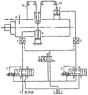
 1-2. Servo valve 3. Electromagnetic reversing valve 4-5. Hydraulic control check valve 6-7. Cylinder 8. Spindle box 9. Front wire rope 10. Rear wire rope figure 1 |
The GIMAX200 CNC floor boring and milling machine jointly designed and produced by our company and French FOREST-LINE company uses static pressure guide rails for each axis movement. The headstock moves up and down through the ball screw belt, and the ram moves in the spindle box. The mast moves inside the ram. For the design of the machine tool, we use the hydraulic balance method to balance the weight of the headstock, and also compensate for the change of the center of gravity of the headstock caused by the movement of the ram and the attachment and attachment. The principle is shown in Figure 1.
In Fig. 1, the cylinder 6 is coupled to a movable pulley, and after the two ropes 9, 10 are wound around the movable pulley, they are coupled to the spindle housing 8 via a pair of fixed pulleys, respectively. The front wire rope 9 is directly fixed to the headstock, and the rear wire rope 10 is coupled to the headstock through the oil cylinder 7. The two servo valves 1, 2 are in communication with the cylinders 6, 7 via the pilot operated check valves 4, 5, respectively. 3 is an electromagnetic reversing valve, which can control the reverse opening of the hydraulic control check valve to return the oil to the cylinder. Among them, the stroke of the cylinder 6 is half of the up and down movement stroke of the headstock, and the pressure on the piston is twice the weight of the headstock. In this balancing system, the weight of the headstock is shared by the two front and rear wire ropes 9, 10.
We can roughly consider the gravity of the headstock and the tension of the front and rear wire ropes as a balancing force system (the frictional force of the hydrostatic guide rail and the ball screw is negligible). When the tool or attachment installed at the end of the ram changes, or when the ram moves within the headstock, the center of gravity of the headstock will change and the original balance force will be destroyed. In order to form a new balancing force system, the tension of the two wire ropes needs to be redistributed. This "task" is mainly done by the two servo valves in Figure 1. The following briefly introduces these two servo valves.
Servo valves 1, 2 are two dual-function valves with position sensors and pressure sensors inside to quickly and accurately adjust flow and pressure. The working process is shown in Figure 2. When the switch is turned on by 1, 2, flow control can be achieved. The position sensor detects the position of the spool, which is represented by the voltage signal u L1 , and is compared with the command voltage signal u QS by the comparator, and the comparison result Δu is stored in the position controller. The position controller controls the movement of the spool by changing the pilot coil current to obtain the required flow. At this time, the feedback voltage u L1 is equal to the command voltage u QS . During this control, the position of the spool is proportional to the command voltage. When the polarity of the command voltage changes, the direction of movement of the spool changes.
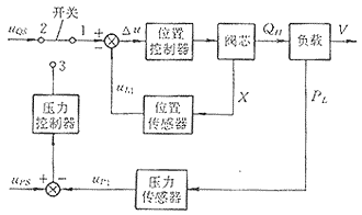 figure 2 |
When the switch is turned on 1, 3, pressure control can be achieved. The pressure sensor detects the pressure P L of port A (Fig. 1), which is represented by the voltage signal u P1 . u P1 is compared with the command voltage signal u P2 and the result is input to the pressure controller. If the two are not equal, the pressure controller outputs a signal that changes the displacement of the spool, thereby changing the flow and ultimately achieving pressure control. In this control process, the A port pressure P L1 is proportional to the value of the command voltage u PS .
In Fig. 1, the servo valve 1 is used to control the cylinder 6. The function of the cylinder 6 is to balance the weight of the headstock assembly. When the speed of the headstock moving up and down changes, we can adjust the flow rate of the input or output of the cylinder 6 by changing the command voltage signal u QS which is input to the servo valve 1. When different tools or accessories are installed at the end of the ram, the weight of the entire headstock assembly (including the tool or accessory attached to the end of the ram) will change. At this time, the pressure of the hydraulic oil supplied to the cylinder 6 can be changed by changing the command voltage signal u PS output to the servo valve 1, so that the headstock assembly can still be balanced.
The servo valve 2 controls the cylinder 7. The function of the cylinder 7 is to compensate for the effects of changes in the center of gravity of the headstock assembly. For example, when the ram is extended outward, the original balance force is damaged due to the forward movement of the center of gravity of the headstock, and an additional overturning moment is generated relative to the original equilibrium position, causing the headstock to lean forward and the front wire rope tension Increase, the tension of the wire rope is reduced. At this time, the hydraulic oil pressure supplied to the cylinder 7 can be reduced by the servo valve 2, the tension of the front and rear wire ropes can be changed, and the overturning moment caused by the extension of the ram can be balanced, so that the headstock is always in equilibrium.
In the servo valves 1, 2, the feedback value measured by the pressure sensor is only the pressure of the servo valve A port (Fig. 1), and this pressure has a certain difference from the pressure in the cylinders 6, 7. This difference is mainly the pressure loss when the hydraulic oil flows through the pipe between the servo valve and the cylinder and the pilot valve. The longer the pipe between the servo valve and the cylinder, the greater the pressure loss. Therefore, the servo valve should be installed as close as possible to the cylinder during assembly, and the hydraulically controlled check valve with a small opening pressure should be selected to reduce the impact of pressure loss.
Since the mast is relatively thin (the diameter of the GIMAX200 mast is 200mm), when the mast is extended, the influence of its own weight deflection must be considered, and how to compensate for this deformation is an important issue. The GIMAX200 solves this problem by the Y-axis displacement compensation method. Each time the mast is extended a certain distance, the headstock is moved up once so that the end of the mast can remain in the theoretical position.
In the above balance and compensation process, the voltage signal output to the servo valve and the compensation amount for the mast sag are calculated according to the theoretical state and then input into the numerical control system. During the actual commissioning process, some accuracy may not meet the requirements due to various factors (such as environmental conditions). At this time, it is necessary to calculate the compensation value according to the amount of sag when the ram and the mast extend a certain distance, and compensate the above control process.
After the above balance and compensation, the GIMAX200 has achieved a fairly good level of precision in the final inspection of geometric accuracy. Wherein, when the ram is extended (the stroke is 1250mm), the straightness in the vertical plane is 0.025mm/1250mm, and the parallelism with the horizontal reference plane is 0.03mm/1250mm; and when the mast is extended (the stroke is also 1250mm) The straightness in the vertical plane is 0.03 mm / 1250 mm, and the parallelism with the horizontal reference plane is 0.03 mm / 1250 mm. After one year of use, re-inspection, found that the accuracy is maintained very well, can fully guarantee the processing accuracy.
Wall Light,Modern Wall Lights,Wall Sconces,Architecture Lamp
Ningbo Royalux Lighting Co., Ltd. , https://www.royaluxlite.com