In the manufacturing process of large parts, there are often some parts working face processing is more difficult. Mainly due to the large workpiece, the clamping is difficult, especially the diameter of some arc surfaces is large, and the shape of the arc is irregular. For the processing of such circular curved surfaces, it is usually necessary to operate the three-axis or three-axis linkage of the numerical control machine to meet the design requirements.
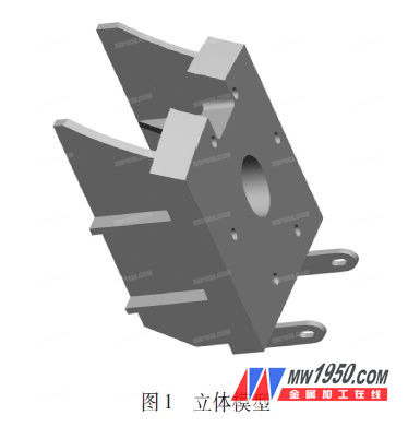
The reversing tool of a steam generator in a hydroelectric generating set is shown in Figure 1. The bottom arc surface of the tool is determined by the circular arc surface of the rotation. Because in the hydro-generator set, some circular arc surfaces of the rotation are particularly important, it involves a combination of the direction of the force and the surface, so the contour of the runner is a typical shaped arc surface. Therefore, the arc surface of the turning forest turning tool must be perfectly matched with the arc surface of the lower ring of the runner, so as to ensure the smoothness of the runner during the turning process.
The use of special equipment to process such irregular arc surfaces can solve the problem, but the special equipment is expensive, and it has great limitations on the type of processed products, and should not be promoted. If such a circular arc surface is processed by a CNC heavy-duty vertical car, the diameter of the runner is generally more than 10m, so the diameter that can be machined by the machine tool is also large, and the number of machine tools capable of machining workpieces with a diameter of 10m or more is now available in China. Not much.
To this end, we have designed a shovel tool that satisfies the design requirements and facilitates the machining of curved surfaces. It can adjust the bolts and attach the arc surface in real time as a “curved surface grinding toolâ€.
1. Arc surface shovel tool principle
The arc surface engraving tool is made of a curved surface to be processed with a bow and arrow using a wrap-around template that can be replaced at any time. During use, the shovel grinding plate is bolted to the beam of the shovel tool, and the adjustment of the long hole is used to keep the template arc in close contact with the workpiece arc surface. The beam can be rotated along the mandrel at the left end of the tool, and the bottom wheel is supported. The radius of rotation is determined by the diameter of the wheel. During the shovel grinding process, the sample is rotated by the beam to determine the shovel allowance of the workpiece. Since there is a scribe line on the sample, the long hole bolt can be adjusted to ensure that the sample is adjusted in real time with the shovel, knowing that the sample reticle reaches the set position. Check the radius of the arc surface of the shovel and the alignment of the arc of the workpiece with the arc of the sample by rotating the beam.
2. Specific implementation
(1) The assembly of the tool is completed according to the assembly schematic of the arc surface grinding tool (see Figure 2).
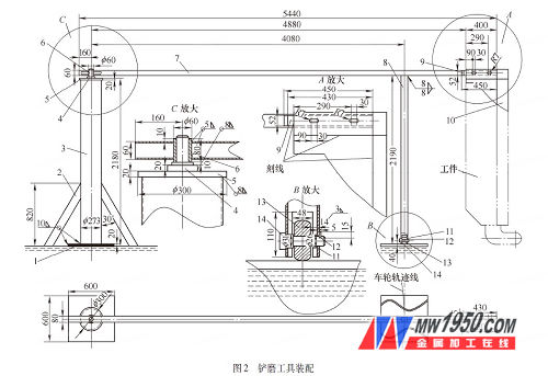

The arc surface shovel grinding device comprises a column 3, a centering shaft 4, a beam 7, a wheel strut 8 and a shovel grinding plate 10. The column 3 is fixed on the platform through the bottom plate 1, and the centering shaft 4 is fixed on the upper end of the column. A small gap on the centering shaft is movably fitted with a centering sleeve 6, and the centering sleeve is welded to one end of the beam 7. Near the Other end, the beam 7 is fixed with wheel struts 8 parallel to the column 3, the lower end of the wheel struts is provided with a through groove for mounting the wheel and a circular hole for mounting the wheel axle 13, and the wheel axle 13 is provided with a wheel located in the through groove 14. The wheel cover 11 is mounted on the wheel axle and freely placed between the wheel end face and the side of the column, and the other end of the wheel axle 13 is fixed to the wheel strut by the shaft end stop 12. On the other end of the beam 7, an elongated hole for adjusting the position of the shovel blade is formed, and a template support 9 having a light hole is welded thereto, and the shovel pattern 10 is fixed on the beam by the template support 9. A gap is provided between the centering shaft and the centering sleeve, and the gap is 0.05 to 0.15 mm.
Kitchen & Bathroom Accessories
Kitchen & Bathroom Accessories,Stainless Floor Drain,Bathroom Bidet Sprayer,Bathroom Jet Sprayer Kit
kaiping aida sanitary ware technology co.,ltd , https://www.kpaidafaucets-jm.com