In the standard parts, automotive and other industries, a large number of shaped parts and standard parts with complicated shapes are used in large quantities, especially in the case of bolt parts. In order to process such parts in large quantities, efficient multi-station bolt automatic forging presses are used. The advantages of the multi-station bolt automatic forging press are high efficiency, saving raw materials and wide range of parts and styles that can be clamped. The same machine can upset a variety of bolt parts of different lengths, but different lengths are cast on the same machine. When bolt parts are used, the problem caused by the change of the length of each part is that the parts or mechanisms such as the mold and the push rod need to be replaced again, and the positional relationship of the threaded sleeves should be adjusted every time, so as to meet the requirements of the part deformation process. Finally, the position of the threaded sleeve is adjusted every time to meet the requirements of the part.
Ask a question
In this respect, the thread sleeve has been manually adjusted with a wrench, and the large-size machine tool is manually adjusted with a special wrench, as shown in Fig. 1.
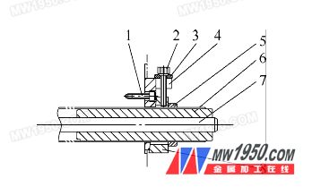
1. Bolt 2. Adjustment bolt 3. Washer 4. Seat plate with bevel 5. Lock nut 6. Push thread sleeve 7. Push rod 8. Wedge iron
For the description of the adjustment method and the locking mode of the push-thread sleeve generally used in FIG. 1, the lock nut 5 is manually loosened when the thread sleeve is required to be moved to the left position, and the adjusting bolt 2 is turned to make all the locking forces disappear. At this time, a wrench or a special wrench is used to adjust the push-out thread sleeve 6 to adjust the threaded sleeve to the left (right) movement through the thread between the bed and the bed to meet the requirements of the workpiece. After adjusting to the ideal position, after the lock nut 5 is locked to the outside of the wedge iron 8, the wedge iron 8 is pulled up by the adjusting bolt 2, and the nut is passed through the inclined surface between the seat plate 4 with the inclined surface. Subjected to the outward force, the purpose of locking the threaded sleeve 6 is achieved.
One of the biggest drawbacks of this adjustment process is that the adjustment of the high-efficiency equipment is complicated and the wrench needs to be replaced several times. Through practice observation, 5 to 10 types are used for adjusting a station to the required position. This is because the pitch of the threaded sleeve is generally fine-sized, and the manual adjustment is not possible due to the limitation of the wrench and other mechanisms. It can only be adjusted half a turn to change the position and then adjust, so the efficiency is very low. For a machine tool that generally has four stations, this adjustment process will take 30 to 45 minutes, which can be seen as a very time consuming process, causing unnecessary work delays and adversely affecting production. If you adjust the automatic adjustment by adding some small organizations, it will greatly save the adjustment time, and you can adapt to the company's adaptive production rhythm.
2. Solve the problem
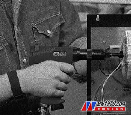
The following describes a high-efficiency adjustment of the position of the threaded sleeve and automatic locking mechanism through research, reference and summary, which realizes the automation of adjustment and locking, which greatly improves the adjustment speed and reduces the adjustment time. Get rid of the trouble of replacing tools such as adjusting wrenches many times, just need a electric gun screwdriver (see Figure 2) to solve the problem.
The simple structure of the designed mechanism is shown in Figure 3.

1. Hydraulic cylinder 2. Locking plate 3. Bearing 4. Supporting seat 5. Gear with keyway 6. Adjusting rod 7. Pushing threaded sleeve
8. Push out the rod 9. Gears fixed at the outer end of the threaded sleeve 10. Bolt 11. Quenching pad
The description of the screw sleeve adjustment method and the locking method is introduced: when the thread sleeve 7 needs to be pushed to the left, the pressure in the hydraulic cylinder 1 is first removed by hydraulic pressure, so that the thread between the locking plate 2 and the push screw sleeve 7 is obtained. The locking force is released. Thereafter, the adjusting rod 6 supported by the bearing 3 is rotated by an electric wrench, so that the keyed gear 5 is rotated, and the gear 5 is meshed with the gear 9 fixed at the outer end of the threaded sleeve, so that the thread is pushed out. The sleeve 7 is rotated to serve the purpose of adjusting the threaded sleeve. It is to be noted that the keyed gear 5 is axially slidable by the radial adjustment of the adjusting rod 6 through the keyway, so that the geared key 5 also moves to the left when the threaded sleeve moves to the left, and continues to be fixed to the thread. The gear 9 of the outer end is engaged. When the adjustment meets the requirements, the hydraulic cylinder 1 is filled with liquid pressure, so that the locking plate 2 is not deformed, so that the thread between the screw sleeve 7 and the threaded sleeve 7 has an outward locking force, ensuring that the automatic locking action is completed. .
3. Conclusion
By applying the Appellate Body to practice, for a four-station machine tool, the threaded sleeve that has been adjusted for four stations can be completed in a maximum of 4 or 5 minutes. It can be seen that the mechanism can greatly improve the adjustment efficiency, and the structure is simple. Without increasing the cost, the automatic adjustment function of the machine tool is added, and the original complicated replacement wrench and the laborious adjustment and locking process are completely lost, so that the adjustment is convenient and fast.
Switches And Sockets,Multi Plug Socket With Switch,Remote Control Plug Socket,Electrical Sockets And Switches
B-F-B-ic international Ltd.co , https://www.ledgather.com