2 magnetic protection
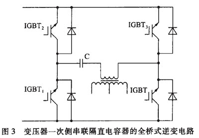
In order to avoid saturation of the magnetic core of the transformer caused by bias, a sufficient air gap can be added to the magnetic circuit of the transformer to improve the linearity of the magnetic permeability, even when the magnetic density is selected in a one-way working state. However, these measures all affect the improvement of the output power of the transformer, and thus cannot reflect the advantages of high utilization of the transformer of the bridge inverter circuit, and also increase the volume and quality of the transformer. A simple and practical method to prevent biasing is to add a DC blocking capacitor on the primary side of the transformer. The circuit is shown in the figure. The DC component of the transformer is blocked by the isolation of the capacitor.
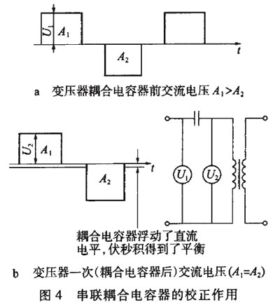
As shown in FIG. 4, before and after the series blocking capacitors, the positive and negative half cycle volts seconds A1 and A2 shown in FIG. 4b are not equal; FIG. 4b shows the series DC blocking capacitor, since the capacitor C floats the DC level, The positive and negative half cycle volt-second products are balanced, that is, A1=A2.
Straight-line capacitors connected in series should use non-polar film capacitors with high frequency performance. The capacitor and the primary side equivalent inductance form a series resonant circuit, and its resonant frequency fR can be expressed as
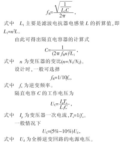
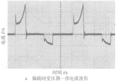
In order to avoid deterioration of capacitor performance caused by heat loss, the equivalent resistance should be as small as possible, and multiple parallel connections may be made if necessary. The specific method is to test the temperature rise of the capacitor during operation, generally should be controlled below a few degrees. After the DC blocking capacitor is used, the biasing problem of the transformer can be solved, so that the working magnetic flux density of the transformer can work close to the saturation point like the power frequency 50Hz transformer, so that the transformer output power of the bridge inverter circuit is high and the utilization rate is high. The features are fully utilized. Figure 5 shows the measured capacitor voltage and current waveforms before and after the DC blocking capacitor is set. It can be seen from Fig. 5b that the primary current of the transformer is obviously unbalanced and has a large peak before the DC blocking capacitor is added; Fig. 5b shows the current waveform after the DC blocking capacitor is added, and the positive and negative half cycle waveforms are substantially symmetrical.
The best way to prevent biasing is to design a special automatic balancing circuit that forces the magnetic flux to be balanced. The schematic diagram of this circuit is shown in Figure 6.
The same current transformer is used on the two bridge arms of the full-bridge inverter circuit, and the magnitudes of the two currents are compared. In the working process, as long as the current imbalance is detected, the width of the power switch tube driving pulse is dynamically adjusted to ensure that the working magnetic flux of the transformer can be symmetric about the origin. This kind of circuit is more complicated than the primary side series blocking capacitor of the transformer, and the production cost is correspondingly higher, but its function of correcting the bias is very strong.
3 Conclusion
The transformer bias problem of the full-bridge inverter circuit should be given enough attention in the design process, not only from the control circuit, feedback circuit, drive circuit and power switching device, but also to avoid imbalance and inconsistency, but also according to actual needs. Different anti-biasing techniques are used.
references:
[1] Huang Shisheng, new arc welding power supply and its intelligent control (1st edition) [M]. Beijing: Mechanical Industry Press, 2000.
[2] Li Aiwen, Zhang Chenghui. Modern Inverter Technology and Its Applications (1st Edition) [M] Beijing: Science Press, 2000.
Previous page
Autoclavable and Universally Compatible PCR Tubes
Ensuring efficient and uniform heat transfer becomes a lot easier with our range of PCR tubes. Thanks to our advanced molding technology, Yongyue Medical can offer you high-quality and uniformly thin-wall PCR tubes at the most competitive prices.
These sterile PCR tubes come with a leakage-proof snap-cap. It allows you to prevent evaporation during the reaction, ensuring accurate results. We use only virgin polypropylene to manufacture the following types of PCR strip tubes.
Types of PCR Reaction Tubes We Offer:
- 0.2ml PCR Tube Flat Cap
More info about PCR Tubes:
What Are PCR Tubes?
PCR tubes are small tubes made of high-quality virgin polypropylene with a conical bottom. They have uniform thin walls to facilitate efficient heat transfer to the sample. These tubes are autoclavable and work well with most thermal cyclers.
What Are the Applications of PCR Tubes?
The most common application of PCR tubes includes various molecular biology biochemistry experiments requiring real-time PCR (Polymerase Chain Reaction). As these tubes have ultra-thin walls, they are perfect for accurate and steady thermal transfer in an array of thermocyclers. Our thin-wall PCR tubes meet the protocols required for PCR, qPCR, reverse transcriptions, and a variety of other applications.
0.2 ml PCR Tubes,PCR Tube Volume,Sterile PCR Tubes,PCR Test Tube,Real Time PCR Tube
Yong Yue Medical Technology(Kunshan) Co.,Ltd , https://www.yonyue-pcrtube.com