1 Introduction
The CAN bus technology was born in the field of automotive control. With the continuous improvement of its technology, the application field has also expanded. Since the introduction of CAN bus technology into China, after the introduction and use stage, since 2000, many domestic manufacturers have made unremitting research and development on the bus technology, and have achieved certain results. At present, the domestic CAN bus technology has been It has been applied in many fields such as automobile control, CNC machine tools, medical equipment and building automation, and is one of the bus technologies that have received extensive attention [1].
The CAN bus has the characteristics of a fieldbus and is suitable for applications in distributed systems. At present, China has a certain development capability of CAN bus products, and its application cost is also reduced. Therefore, CAN bus technology has been widely used in the transformation of traditional control systems. With the reform of thermal energy commercialization and heating billing system, the domestic residential heating system will also change, the most important and most difficult is the transformation of the heating metering system. In the newly built residential quarters, different heating methods can be adopted according to the requirements of the current national heating system, and the design of the residential district heating system is carried out according to the specific heating method. However, how to reconstruct the old residential heating metering system with large stocks It is a difficult point, because this may involve the transformation of existing heating pipelines, and the engineering volume of heating pipelines is relatively large, and the construction period is long. In particular, the pipeline transformation has a great impact on the residents, and it may be relatively large in implementation. Resistance [2, 3]. Therefore, according to the requirements of the renovation of the old residential heating system, it is necessary to design a simple and practical residential heating metering system. This paper completed the design of a heating metering system based on CAN bus technology.
2 CAN bus technology introduction
2.1 CAN bus structure CAN (Controller Field Bosch introduced a fieldbus standard in 1990. It has the characteristics of strong real-time performance, high reliability, and low development tools. Motorola, Intel, Philips and other companies provide hardware support. .
The CAN bus system is composed of many CAN nodes. The CAN bus connects the various nodes, and the total length of the bus is up to 10 kilometers. The CAN bus can be connected to the upper network through a Linking Device, which can be an information network or other standard bus.
The CAN bus protocol follows the OSI model, and its data link layer and physical layer are described by the CAN 2.0 protocol specification. The CAN2.0 protocol specification does not describe the application layer of the CAN bus protocol, so its application layer needs to be built separately [4].
2.2 CAN bus node CAN bus node consists of three parts: microprocessor system, CAN controller and CAN bus transceiver. The CAN bus node composition and connection diagram is shown in Figure 1.
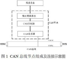
The microprocessor system in the node is composed of a microprocessor and a local application circuit. The microprocessor is the control center of the entire node. The local application circuit is connected to the field device. The CAN transceiver in the node is connected to the CAN bus, and the CAN bus node is connected to the site. The key to equipment and bus.
The CAN bus node has two important functions: bus communication function and local control function. The bus communication function completes the data transmission with other nodes on the bus; the local control function completes the control of the field device connected to the node. The node plus the field device constitutes a control system, and is a control system with communication function. The CAN bus is an information channel that connects many such control systems together, and the system constructed by the CAN bus technology is a distributed system, which embodies The nature of fieldbus technology [5, 6].
3 overall design
3.1 Demand and technical analysis China's central heating system is mainly used in building residential buildings. At present, although the heating methods in old houses are different, the basic structure of the heating pipes is the so-called “continuous chainingâ€. According to the different heating areas in the house, each heating line is distributed in different locations in the house. Each radiator in each layer above and below is connected with a radiator. The structure of the single-layer single-heating pipeline is shown in Figure 2. .
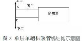
The equipment layer of the house is provided with a horizontal return line. For example, at least 6 heating pipes in a two-bedroom, two-bedroom, one-bath kitchen unit pass through, and must be changed for each household without changing the existing heating pipeline. The amount of heat consumed by each pipeline is measured separately, that is, the amount of heat consumed from point A to point B in Figure 2, and the total heat consumed by the household is obtained after accumulation. Due to the spatial distribution, the heating metering system must adopt a fully distributed system. The CAN bus technology meets this requirement, and the CAN bus product has lower cost than other fieldbus products, and is suitable for the transformation of existing systems. The CAN bus technology is adopted in the design. In the residential buildings, the consumption of calories should be measured. Generally, the system should measure the flow rate and temperature of the corresponding heat transfer medium. Therefore, the ends of each household's single heating line, that is, points A and B in Figure 2 should be set. There are flow and temperature measurement points, based on the difference in flow rate and temperature difference between the two places, the heat consumed by the radiator of the household can be calculated. To simplify field devices, the calculation of calorific value is done in the host. The unit house has the characteristics of layer by layer. In this kind of house, each household's single heating line can set a measuring point to meet the measurement requirements, such as a 21-storey residential building with one floor heating. The number of measuring points on the line is 22. If each floor is calculated by 10 households and each household has 6 heating lines, the residential building has a total of 1320 measuring points.
3.2 Overall scheme design The master/slave structure is adopted in the system design. The system structure block diagram is shown in Figure 3. The host is connected to the CAN bus through the CAN bus adapter, and the node adopts a unified power supply mode. The terminator is required by the CAN bus and is installed at both ends of the bus. Node 1 to node n are CAN bus nodes, which mainly collect the flow value and temperature value and communicate with the host. The system has the function of automatic data collection, which avoids the process of manual table lookup.
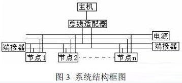
The host accesses the node by means of inspection. The accumulation of traffic is done in the node, and the temperature value is collected by the node for the host to read. The maximum length of the bus can reach 10 kilometers, which is sufficient for the current high-rise residential requirements.
Under normal heating conditions, if there is no leakage, the flow rate on the single heating line should be equal. Since the horizontal return line is in the equipment layer, the flow sensor is only installed at the equipment level, and the flow value at these points is in the household. The flow values ​​are equal, which can reduce the amount of engineering work, and the disadvantage is that the leakage of the household heating facilities cannot be detected. A temperature sensor is installed at each measurement point. For example, a residential building with a floor height of 21 floors has its equipment layer in the top and middle layers, so nodes are installed at the top, bottom and middle equipment layers.
The temperature sensor is installed at each measuring point. The temperature sensor cable and the CAN bus (using unshielded twisted pair) must pass through the upper and lower floors of the household along the heating pipeline. If the wireless system is used, the wiring can be avoided and the impact on the residents can be reduced. However, from the perspective of system reliability and stability, the cable system was finally selected.
4 node hardware and software design
4.1 Node Hardware Design In the CAN node hardware design, the 89C51 single-chip microcomputer is used as the processor, and the CAN controller and the CAN transceiver select the SJA1000 and 82C250 of the widely used Philips company. The block diagram of the node hardware is shown in Figure 4. The node has the functions of flow value accumulation, temperature acquisition, power display and power-down protection, optical alarm and bus communication.
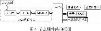
The temperature sensor uses the digital temperature sensor DS18B20 manufactured by DALLAS, USA. The sensor has a temperature range of -55 to +125 ° C and a temperature resolution of 0.0625 ° C, with a measurement accuracy of ±0.5 ° C in the range of -10 ° C to +85 ° C, since each DS18B20 has a unique one. Continuous 64-bit product number, so that under the control of the microprocessor, multiple sensors can be connected to one cable. The longest cable length can reach 150 meters, which can meet the requirements of system design [7].
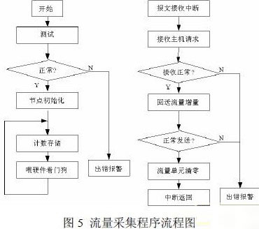
4.2 Node Software Design Node software consists of three parts: node communication program, temperature acquisition program and flow collection program. Here is a brief introduction to the flow collection program. In the northern part of China, a heating season is about 150 days. If the accumulated value of the flow is 8 decimal digits, the flow count can be up to 9999999.9 tons, which can meet the requirements of most applications. In the design, the accumulated count of node traffic is in the form of uncompressed BCD code. A total of 8 units are used. The unit starting from 60H-67H in the 89C51 microcontroller is used as the accumulating unit of software counting, of which 60H is the lowest 8 bits. Traffic collection needs to record the accumulated value of traffic, so the continuity of its work is very important, but when the node itself fails, the accumulated value of the current traffic will be lost. At this time, only the last time in the host is in the entire system. The cumulative value of the traffic sent by the node is collected. Therefore, the software design of the traffic collection node should consider how to recover the accumulated value of the traffic when the node fails to be used again. The software design uses the on-site traffic collection to measure the traffic only. Incremental value, the way the host performs the accumulation after reading. The flow chart of the node traffic collection program is shown in Figure 5.
5 Conclusion
The heating metering system based on CAN bus technology designed in this paper is suitable for the renovation of the old residential heating system in China. The test system has been run in a five-storey office building with a building area of ​​about 6,000 square meters. In a heating season, the reliability and metering accuracy of the system meet the design requirements. The renovation of the old residential heating metering system is the key and difficult point of China's heating system reform. I hope that the work of this paper can provide some experience for the renovation of the current residential heating system.
Magnetostrictive level sensor is composed of three parts: probe rod, circuit unit and float. To measure, the circuit unit generates pulses of current that travel down the magnetostrictive line and generate a circular magnetic field. A float is arranged outside the probe rod, and the float moves up and down along the probe rod with the change of liquid level. The float generates a magnetic field at the same time because it is fitted with a set of permanent magnets. When the current magnetic field meets the float magnetic field, it produces a "twisting" or "return" pulse. The time difference between the "return" pulse and the current pulse is converted into pulse signals to calculate the actual position of the float and measure the liquid level.
Magnetostrictive Level Sensor,Magnetostrictive Level Transmitters,Magnetic Type Level Gauge,Liquid Level Sensor,Magnetostrictive Level transmitter
Xi'an Gavin Electronic Technology Co., Ltd , https://www.gamicos-meas.com