1 Scope
This standard stipulates the definition, classification and naming, use conditions, technical requirements, test methods, inspection rules, signs, operating instructions, packaging, transportation and storage of solar lighting products.
This standard applies to solar voltage lamps with voltages of 24V and below.
2 normative references
The clauses in the following documents have been adopted as references to this standard. For dated references, all subsequent amendments (not including errata content) or revisions do not apply to this standard, however, encourage the parties to reach an agreement based on this standard to study whether the latest version of these documents can be used . For undated references, the latest version is applicable to this standard.
GB/T 191-2000 packaging, storage and transportation icon logo
GB/T 2423.1-2001 Environmental testing for electric and electronic products Part 2: Test methods Test A: Low temperature
GB/T 2423.2-2001 Environmental testing for electric and electronic products Part 2: Test methods Test B: High temperature
GB/T 2423.3-2006 Environmental testing for electric and electronic products Part 2: Test methods Test Cab: Constant damp heat test
GB 7000.1-2002 general safety requirements and tests for lamps
GB/T 19064-2003 Technical requirements and test methods for domestic solar photovoltaic power systems
QB/T 1553-1992 Lamp Corrugated Carton Packaging Technical Conditions
3 Terms and Definitions
The following terms and definitions apply to this standard.
3.1
Solar lighting
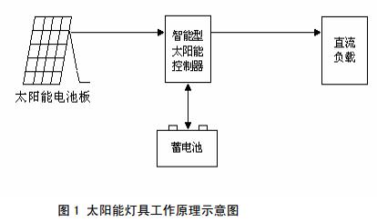
The solar lamp is a miniaturized solar photovoltaic system. The solar panel is facing the sun and realizes photoelectric conversion. The controller stores the electric energy in the battery. At night, it uses the controller to provide electricity for the lamp. Battery components, batteries, controllers, and electric light sources.
3.2
Components
It refers to the smallest integral solar cell combination device with a package and internal connection that can independently provide a DC output.
3.3
Light control
The use of the voltage change of the solar cell as a light source control signal to control the switching of the solar lamp.
3.4
Time control
Timing control of solar lighting switch method.
3.5
Charge and discharge controller
An apparatus for overcharging or overdischarging an energy storage battery pack that automatically prevents solar photovoltaic power supply systems.
4 Classification and Naming
4.1 Classification
According to its use, the product is divided into: solar street lights, solar garden lights, solar landscape lights, solar lawn lights, and solar underground lights.
4.2 product model life
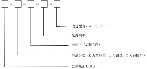
5 conditions of use
5.1 Conditions of Use
a) Ambient temperature of street light, garden light and landscape light: -20°C~+60°C, relative humidity: 0~85%;
b) ambient temperature of lawn and buried lights: -20 °C ~ +60 °C;
c) Sites without corrosive substances or destructive substances.
5.2 Working principle
Solar lighting works as shown in the figure:
6 Technical Requirements
6.1 Appearance
The surface of the product should be smooth and smooth, with uniform color; the product has no obvious cracks, scratches, damage, rust and deformation; the main surface paint film should not have obvious sagging, blistering, orange peel, pinhole, bite bottom, bleed Impurities and other defects.
6.2 paint adhesion
The paint film should have good adhesion, and the paint film and the substrate should be combined firmly. After the film adhesion test, there should be no phenomenon of film peeling off.
6.3 Structure
6.3.1 Luminaires containing replaceable parts or components should be designed with sufficient space to allow safe replacement of these parts or components.
6.3.2 cabling groove should be smooth, no sharp edges, burrs, burrs and other similar phenomena.
6.4 voltage
6.4.1 When the battery voltage is 12V, the battery full-state voltage is not less than 12.8V.
6.4.2 When the battery voltage is 24V, the full battery voltage is not less than 25.6V.
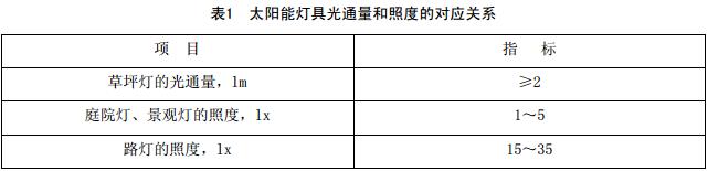
6.5 Luminous flux and illumination
The luminous flux and illuminance of solar lamps should meet the requirements in Table 1.
6.6 Solar Light Control
The light control function of solar lamps should be normal. When there is no sunlight, the light intensity drops to the starting point, and it automatically emits light within ±5% of the set starting value. When there is sunlight, the light intensity rises to the starting point and is automatically within ±5% of the set starting value. Charging.
6.7 Solar Lighting Control
The time control function of the solar lamp should be normal. According to the set time, the time error of the lamp lighting should be less than 5s.
6.8 Solar Lighting Charge and Discharge Performance
Under good lighting conditions, charging for more than 8 hours during the day can ensure normal lighting for 3 consecutive rainy days.
6.9 Charge and Discharge Controller
6.9.1 Protection function: When the following conditions occur, the controller should be able to protect and automatically recover after the protection is eliminated.
a) load short circuit;
b) Reverse polarity of load, solar module or battery;
c) internal short circuit of charge and discharge controller and other equipment;
d) Breakdown due to lightning strikes in multi-zones;
e) The battery is reversed through the solar module.
6.9.2 The controller itself should have the function of full battery disconnect (HVD) and undervoltage disconnect (LVD).
1) The controller has the function of input full disconnect and resume connection
a) 12V sealed lead-acid battery, full of disconnected HVD: 14.1V ~ 14.5V, recovery: 13.2V;
b) 24V sealed lead-acid battery, full of disconnected HVD: 28.2V ~ 29.0V, recovery: 26.4V.
For controllers with VR, it should be able to work normally within the preset range after full charge.
2) The controller has under voltage disconnect (LVD) and recovery functions. When the battery voltage drops to the overdischarge point ((1.80±0.05)V/only) the controller should be able to automatically cut off the load; when the battery voltage rises back to
When the charge recovery point ((2.2-2.25)V/only), the controller should be able to automatically or manually restore the power supply to the load.
6.9.3 No-load loss (quiescent current)
The maximum power consumption of the controller must not exceed 1% of its rated charging current.
6.9.4 Charge and discharge loop pressure drop
The voltage drop across the controller for charging or discharging must not exceed 5% of the system's rated voltage.
6.9.5 Impact Voltage
When the battery is disconnected from the circuit, the controller must withstand 1.25 times the nominal open circuit voltage of the solar module within 1 hour.
6.9.6 Inrush Current
The controller must be able to withstand 1 h higher than the 1.25 times the nominal short circuit current of the solar module. Switching controller switching components must be able to switch this current without damaging it.
6.9.7 Environmental Test
6.9.7.1 Low-temperature operation test: After the low-temperature test according to GB/T 2423.1-2001, the controller shall be able to work normally.
6.9.7.2 High-temperature working test: After high-temperature test according to GB/T 2423.2-2001, the controller should be able to work normally.
6.9.7.3 Constant Damp Heat Test: After a constant damp heat test according to GB/T 2423.3-2006, the controller shall be able to operate normally.
7 test methods
7.1 paint adhesion test
Measured using an adhesion tester.
7.2 Battery voltage
Use a voltmeter to measure the battery voltage.
7.3 Luminous flux and illumination
7.3.1 Luminous flux: Measured with a photometer.
7.3.2 Illuminance: Turn on the illuminometer and place the photometric surface of the illuminometer directly on the light source and place it on the road surface. The displayed value is the illuminance value of the luminaire.
7.4 Solar Light Control
Light control function simulation: If it is in the daytime, after the wiring, opaque objects can completely block the light-receiving surface of the battery module (or remove the battery module wiring on the controller), according to the delay time mentioned in the manual (usually 5 minutes), after seeing the corresponding time, whether the lamp can automatically light, can light that the light control function is normal, can not be lit, it means that the light control function is invalid.
Light control function simulation: According to the above operation, remove the shield on the solar module (or connect the power cable of the battery module on the controller), and the light source can be extinguished automatically, which means that the light control function is normal.
7.5 solar lighting control
Set time to control the time, observe the light source and turn off, according to the set time, use the timer to time.
7.6 Solar Lamps Charge and Discharge Performance Test
Under the outdoor natural environment conditions, the lighting system is set to working status and the working status of the entire system is inspected, which should meet the requirements of 6.8 of this standard.
7.7 Solar Lighting Controller
7.7.1 Protection Features
a) Load short-circuit protection: Check whether the output circuit of the controller has a short-circuit protection circuit.
b) Internal short circuit protection: Check the controller input circuit for short circuit protection circuit.
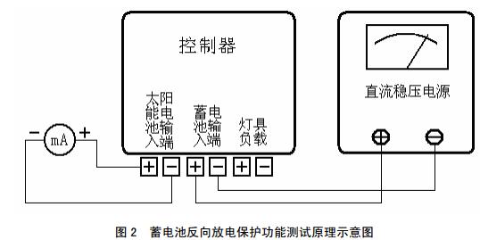
c) Reverse discharge protection: The test circuit is shown in Figure 2. The ammeter is added between the positive and negative terminals of the solar cell module (equivalent to short-circuiting the solar cell module), and the voltage of the DC power supply connected to the battery terminal is adjusted to the rated voltage, and the milliampere meter reading is measured. If there is no current, there is reverse discharge protection.
d) Reverse Polarity Protection: The DC voltage stabilized power supply that is adjusted to the rated voltage will be connected to the solar energy of the controller and the input terminal of the battery. Check whether the DC stabilized power supply is overcurrent and protected; if the controller is damaged.
e) Lightning protection: Visually inspect the type and rating of the arrester to ensure that the expected impact energy is absorbed.
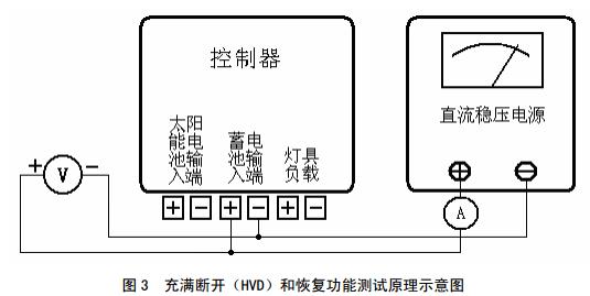
7.7.2 Full Disconnect and Restore Function
The test circuit is shown in Figure 3. Connect the DC power supply to the input of the battery and connect the current meter to the battery circuit to simulate the battery voltage. Adjust the voltage of the DC power supply so that it reaches full HVD point, the controller should disconnect the charging circuit; reduce the voltage to restore the charge point, the controller should be able to reconnect the charging circuit.
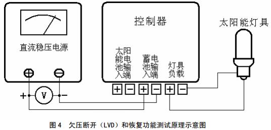
7.7.3 Undervoltage Disconnect (LVD) and Resume Functions
The test circuit is shown in Figure 4. Connect the DC power supply to the battery input to simulate the voltage of the battery; connect the solar lamp to the load. Then adjust the voltage of the DC power supply to undervoltage. The LVD point controller should be able to automatically disconnect the load and adjust the voltage to the recovery point. The controller should be able to turn on the load again.
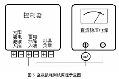
7.7.4 No-load loss (quiescent current)
The test circuit is shown in Figure 5. Disconnect the PV input and load output. The DC power supply is connected to the battery side of the controller. The input current of the measurement controller should meet the requirements of 6.9.3 of this standard.
7.7.5 controller charge and discharge loop voltage drop
7.7.5.1 Adjust the controller charging circuit current to the rated value, and use a voltmeter to measure the voltage drop of the controller charging circuit, which shall meet the requirements of 6.9.4 of this standard.
7.7.5.2 Adjust the controller discharge loop current to the rated value, and use a voltmeter to measure the voltage drop of the controller discharge loop, which shall meet the requirements in 6.9.4 of this standard.
7.7.6 Impact Voltage
Apply the DC power to the solar cell input of the controller and apply 1.25 times the nominal voltage for 1 hour. The power-on check controller should not be damaged.
7.7.7 Inrush Current
Connect the DC power supply to the charging input of the controller, connect the variable resistor to the battery terminal, and adjust the resistance so that the charging loop current reaches 1.25 times the nominal current for 1 hour. After the power is turned on, check that the controller is not damaged.
7.7.8 Environmental Test
7.7.8.1 Low-temperature working test: The test method is carried out according to "Test A" in GB/T 2423.1-2001. The test temperature is (-5 ± 3) °C. After the power is applied and the rated load is maintained for 2 hours, the controller shall be able to work normally after recovering for 2 hours.
7.7.8.2 High-temperature working test: The test method is carried out according to "Test B" in GB/T 2423.2-2001. The test temperature is (40 ± 2) °C, the power is applied and the rated load is maintained for 2 hours, and after 2 hours recovery, the controller should be able to work normally.
7.7.8.3 Constant Damp Heat Test: The test method shall be conducted in accordance with the "Test Cab" in GB/T 2423.3-2006. The test temperature is (40±2)°C, the relative humidity is (93±3)%, the test duration is 48 hours, and the controller should work normally after 2 hours recovery.
8 inspection rules
8.1 Inspection Classification
Solar lighting inspection is divided into factory inspection and type inspection.
8.2 factory inspection
8.2.1 The solar lighting fixtures should be tested one by one after leaving the factory and can only be delivered after inspection by the quality inspection department.
8.2.2 The factory inspection project shall be conducted in accordance with the requirements of 6.1, 6.3, 6.4 and 6.5 of this standard.
8.3 type test
8.3.1 When the product has one of the following conditions, type inspection should be carried out:
a) When a new product or an old product is converted into a production test,
b) After the formal production, if the structure, materials, and processes are greatly changed, the product performance may be affected;
c) The product was discontinued for more than two years and resumed production;
d) When the national quality inspection and supervision agency proposes the requirements for type inspection;
e) In the normal production situation, a type inspection shall be carried out at least two years.
8.3.2 Type test items are to be carried out according to all the items specified in Chapter 6 of this standard.
8.4 decision rules
8.4.1 The factory inspection is in conformity with the requirements specified in 6.1, 6.3 and 6.4 of this standard.
8.4.2 All types of inspections conforming to the provisions of Chapter 6 of this standard are qualified, otherwise the type inspection will be ineligible.
9 signs and instructions
9.1 mark
Each solar powered lighting fixture shall be provided with a signage. The signage of the signage shall be clear and tidy. The product signage shall include the following contents:
a) the name of the manufacturer;
b) product name;
c) product model and mark;
d) Product main parameters;
e) Factory date and factory number.
9.2 Product Instruction
Solar lamp products should generally be accompanied by product specifications. The instructions should include all the items in 9.1. In addition, the following should also be included:
a) product use precautions;
b) installation instructions;
c) maintenance.
10 Packaging, Transport and Storage
10.1 Packaging
10.1.1 Solar lighting packaging should meet the requirements of QB/T 1553-1992.
10.1.2 The logo design of the packing box shall comply with the provisions of GB/T 191-2000.
10.1.3 The box should also include the following:
a) Manufacturer's name and address;
b) product name;
c) trademarks;
d) product marking;
e) product quantity;
f) Overall dimensions (length × width × height);
g) the quality of the whole box;
h) Manufacturing date or production lot number.
10.1.4 The packing box should have a packing list, a product specification, a certificate, an attachment and related random documents.
10.2 Transportation
During the process of loading, unloading and transportation, the product shall not be subjected to strong jolts or vibrations, nor shall it be exposed to moisture or rain.
10.3 Storage
10.3.1 The product should be stored in a ventilated, dry warehouse.
10.3.2 The product must not be mixed with flammable substances and chemical corrosion products.
Fulcrum Mini Electric Hoist,Mini Electric Wire Rope Hoist,Mini Electric Rope Hoist,Mini Electric Cable Hoist
Guangdong Gongyou Lift Slings Machinery CO.,LTD , https://www.wmpallettruck.com