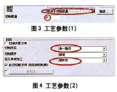
The blade profile milling adopts a tapered ring cutter (diameter 3mm, cutting edge length 30mm), as shown in Fig. 2. The solution for machining one impeller single blade type—2 contour milling between curves, the tool milling range is controlled in two curves Between, the choice of cutting type "depends on the number of cuts", the amount of cutting is controlled by the number of cuts, resulting in a cutting path, see Figure 3. The cutting method is “single pathâ€, and the type defined by the single 'direction is “clockwiseâ€. The above two parameters can be defined according to the process requirements, and the specific shape of the blade should also be considered, as shown in Figure 4.
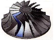
Figure 1 integral impeller
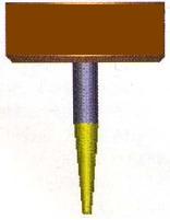
Figure 2 Conical tool
1 Define geometry
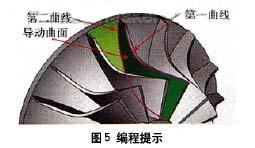
Select the outer edge of the blade as the "first" curve, select the inner edge of the blade as the "second" curve, and select the curved surface between the two blades as the "guided surface". The above three items are mandatory and are the basics of generating "code". Claim.
The "first" curve limits the surface processing trajectory by the contour of the space, so that the trajectory is added in the restricted area 1; the "second" curve limits the surface processing trajectory by the contour of the space, so that the trajectory is in the restricted area 2 Machining; "guided surfaces" define the surface objects being machined on the product, as shown in Figure 5.
2 Define the tool axis control
The tool axis tilt mode is defined as "tilt according to the cutting direction". Considering the need to use the tool side edge for machining, it is necessary to properly control the tool axis vector. The inclination of the cutting direction is such that the tool produces a tool path along the natural course of the curved shape, and the parts machined by such a tool path are smoother. Set the "inclination angle in the cutting direction" to 85°, which mainly considers the taper angle of the cutting tool (using the side edge of the milling cutter to machine the curved surface of the space, which can greatly improve the finishing efficiency of the curved surface) 6.
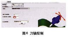
Note that the above value is 85°, which will allow the machine to continuously watch the machine simulation. The rotation mentioned here is due to the interference check. When we use 80° or 85°, we observe the tool change and the machine tool changes in the machine simulation and compare them. The tool cone angle is changed to 2.5°, and the settings are re-set to compare the differences.
3 Define interference check
Define the first interference check option: Select the guide surface as the interference check surface, and the system will automatically add the surface as the interference check surface. The application of this situation is mainly to solve the phenomenon that the twisted guide surface interferes with the tool after being processed, as shown in Fig. 7.
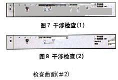
Define the second interference check option: select the surface between the two blades again as the second interference check surface, the tool will interfere with “retraction along the direction of the tool axisâ€, and the inspection surface refers to the interference surface of the tool used for space surface machining. See Figure 8.
Next page
We are a company specializing in fountain and waterscape. Our main business includes: various kinds of music fountains, light shows, digital water curtains, water curtain movies and other fountains.We can provide professional design, production, installation, commissioning and other services.This category is mainly music fountains,today,music fountain is widely used.
Music Fountain,Musical Fountain,Musical Water Fountain,Musical Dancing Fountain
Wuxi Jinshanghua Environmental Equipment Co., Ltd , https://www.jshfountain.com